I design my pipeline tools for longevity. I want both the artist and the programmer to easily extend the tool’s use to be applicable as project goals shift over time.
On the software side, this means leveraging inheritance and composition of classes where possible to streamline applicability to new characters or assets.
For the artist, data structures like rig systems and skeletons can be created with Pyside UI tools, then saved out as templates to be reused as starting points for more complex assets in the future.
Specific applications of these design principles are discussed in the project breakdowns below.
Skeleton Editor
This tool is used to help make the process of bind skeleton and weight painting bidirectional for ease of iteration. When authoring a skeleton, each joint needs specific attribute values for rotation orders, transformations, parent-child relationships, etc.
My approach is to represent joints by creating stand in guides. These can be assigned parent relationships with the UI that will inform the tool when creating the final hierarchy. This parenting effect is only visual for the guides, so all of them can still be moved without having to worry about disturbing downstream nodes.
The tool can be given templates to search for specifically. If guides in the scene are assigned the human_arm module parent attribute, when the guides are converted to joints, those arm guides will be oriented as defined in a preset. For this example, a human arm is expected to share a coplanar relationship for IK setups, so this will be automatically applied.
Joints can at any point be converted back into guides, so adjustments can be made, and the orientations will be recalculated.
Usually, the need for moving a joint is determined when testing skin weights. For this reason, the tool is able to temporarily hold the weights on the joints while the locators are being moved. When turned back into joints, the skin cluster is recreated and the weights are assigned 1 to 1.
The artist is intended to have the freedom to build out their rig for any custom creature. If there is a preset that will likely be needed again, it can be saved out and brought in for other characters.
Auto Control Rig
Code samples on my GitHub.
My Control Rig tools are designed to able to expand to any rig type. The Python code structure allows the system to be extended by creating new module classes from an abstract base class that defines generalized creature parts like arms or legs. This way, a standardized character type like a human only needs to be designed for once, and then any future character with a similar skeletal structure can reuse the script logic. Artists who use the tool are also given the ability to package the work they have done into template .json files, so rigging logic like FK/IK, and control shapes can be saved and standardized between rigs.

Module Builder
The first tool is a PySide2 UI that allows the user to create and define modules, control system logic, and connections between body parts. When the UI is opened, it checks the scene for bind joints with specific string attributes that define what module they belong to. If they exist in the scene, the UI pulls a reference to the corresponding module class from a registry and allows the user to interact with its methods.
Nodes are given a variety of extra attributes when created, so their identity is more specific then their string name or kNode internal identity. Joints can be bind joints, driver joints, FK joints, etc., which makes them easier to find by helper functions.
All node logic is done with matrix math, meaning no Maya constraints are used in my rigs. This allows be to have flat hierarchies for performance gain, and cleaner node connections.
The tool is designed to give more bidirectional freedom to the user than Maya usually allows. If an arm is given the FK and IK features, a switch is automatically created for that module. If the user later wants to remove the FK feature, the tool responds to this by removing the FK and the switch, while leaving the IK fully functional.
If the setup reaches a point that would make a good foundation for future rigs, the user can make a .json template file with “Save as Template.” This can be read by the UI later to call all of the same methods to make the same rig with the “Load Template” button.
Templates add module logic and temporary curves to be replaced later.
Shape Factory
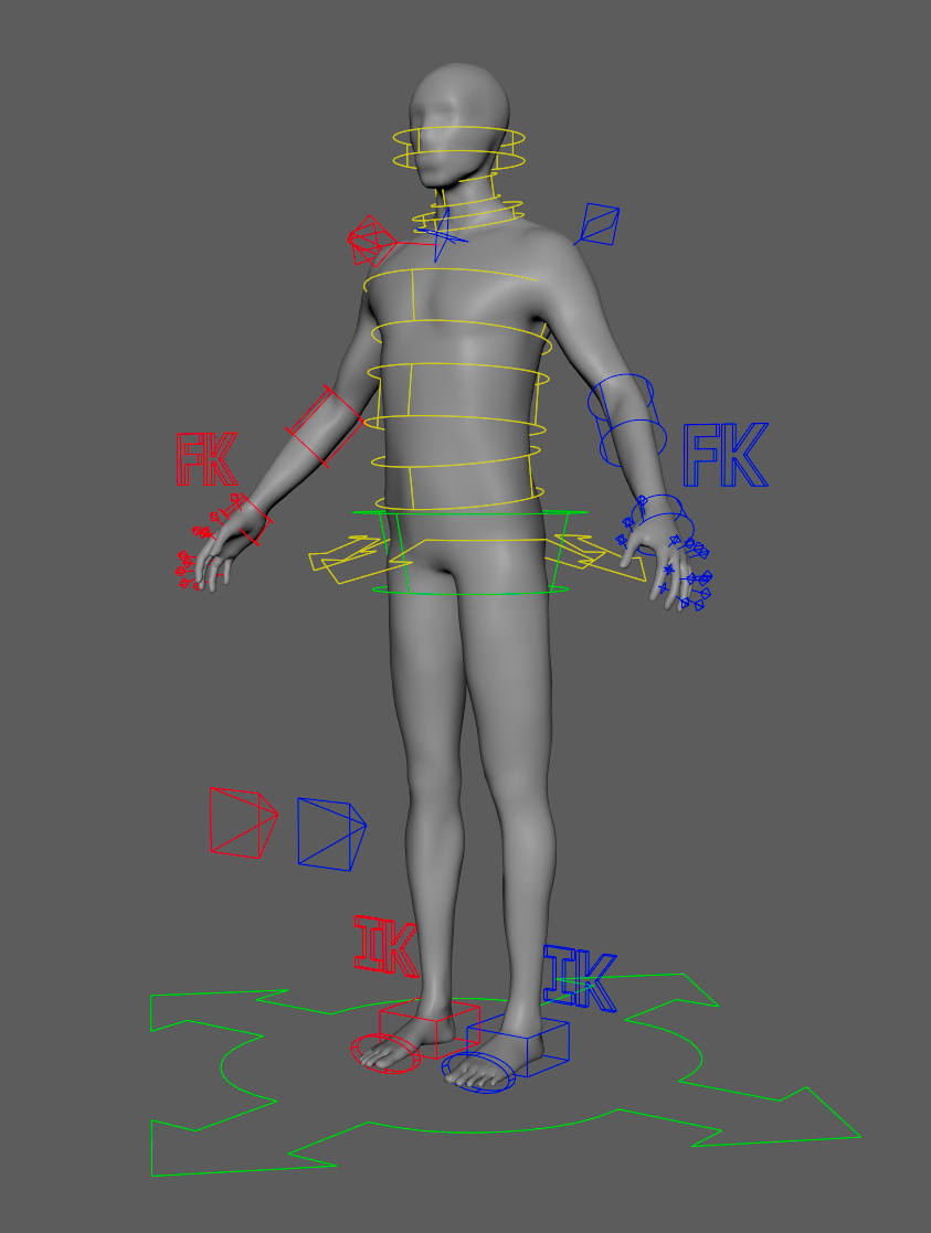
Feature systems created with the Module Builder leave temporary NURBS circles that can be replaced using the Shape Factory. The user selects one, and then chooses a base shape, a starting scale, and a line thickness. From there, the CVs can be transformed for additional design, and assigned a color. Shapes can be mirrored with the “mirror” button, respecting the shape and orientation, as well as assigning the color standard (red on right side, blue on left).
As with the Module Builder, a template file can be created that holds the NURBS data for all shapes in a rig, like CVs, knots, degree, etc. This can be loaded again on future rigs. Because the NURBS are rebuilt from their primitives with OpenMaya, any shape design can be saved without issue.
Select a .json template created earlier to automatically recreate the control shapes.